Technical drawing serves as the universal language that transforms your creative design concepts into precise, manufacturable realities. Whether you’re an architect sketching building plans, a product designer developing the next innovative gadget, or an engineer creating mechanical components, mastering technical drawing skills is essential for professional success.
Technical drawing bridges the gap between your imagination and actual production by providing standardized methods to communicate exact specifications, measurements, and construction details to manufacturers, clients, and team members. This visual communication system has evolved from manual drafting with traditional instruments to sophisticated computer-aided design software, but the fundamental principles remain unchanged.
Your ability to create clear, accurate technical drawings directly impacts project outcomes and collaboration effectiveness. The standards and conventions you’ll learn apply whether you’re working with pencil and paper or the latest CAD software, making technical drawing skills a valuable investment in your design career.
Key Takeaways
- Technical drawing is the essential communication tool that translates design ideas into precise, actionable instructions for production
- Modern technical drawing combines traditional drafting principles with advanced software tools to enhance accuracy and collaboration
- Mastering technical drawing skills improves your ability to communicate design intent clearly across all project stakeholders

Understanding Technical Drawing in Design
Technical drawing serves as the visual language that bridges the gap between design concepts and physical production. These precise graphical communications enable designers to convey detailed specifications to manufacturers and engineering teams.
Definition and Scope of Technical Drawing
Technical drawing is the specialized practice of creating precise visual representations that communicate how objects function or should be constructed. You create these drawings to convey exact dimensions, materials, and assembly instructions.
The scope extends beyond simple sketches. Technical drawings include detailed specifications for manufacturing processes, assembly sequences, and quality control standards.
You use standardized symbols, line types, and projection methods to ensure universal understanding. These conventions eliminate ambiguity between design intent and final production.
Modern technical drawing encompasses both traditional drafting methods and computer-aided design tools. Digital platforms allow you to create more accurate drawings with integrated calculations and automatic updates.
Importance for Designers and Manufacturers
Technical drawings serve as the primary communication tool between your design vision and manufacturing reality. Manufacturers rely on these documents to understand exact specifications without guesswork.
You reduce production errors significantly when providing clear technical drawings. Precise dimensions and assembly instructions minimize costly manufacturing mistakes and material waste.
These drawings also serve legal purposes in design contracts. They establish clear expectations and deliverables between you and manufacturers or clients.
Quality control processes depend on technical drawings as reference standards. Inspectors use your drawings to verify that finished products match design specifications exactly.
Types of Technical Drawings Used in Design
Orthographic projections show objects from multiple fixed viewpoints using parallel projection lines. You typically create front, top, and side views to display all necessary dimensions.
Isometric drawings present three-dimensional objects in a single view with equal emphasis on all three axes. These help visualize spatial relationships and overall form.
Sectional views reveal internal components by cutting through objects along specified planes. You use these when external views cannot show critical internal features.
Detail drawings focus on specific components or connections requiring additional clarification. These provide enlarged views of complex areas with precise dimensional information.
Assembly drawings show how individual parts fit together in the complete product. You include part numbers, assembly sequences, and critical alignment information.

Key Principles and Conventions
Technical drawings rely on standardized principles that ensure your designs communicate clearly across industries. These conventions establish uniform approaches to precision, line work, and documentation that make your drawings universally readable.
Precision and Accuracy in Technical Drawings
Precision forms the foundation of effective technical drawings. Every measurement, angle, and proportion must reflect the exact specifications of your design intent.
Your drawings should maintain consistent scale relationships throughout all views. This means every dimension corresponds directly to the actual object size when multiplied by the scale factor.
Geometric accuracy requires proper orthographic projection techniques. Each view must align perfectly with adjacent views to show the true shape and size of features.
Tolerance specifications define acceptable variation ranges for manufactured parts. You need to include these limits when precision requirements affect functionality or assembly.
Common precision requirements include:
- Dimensional tolerances (±0.1mm, ±0.005″)
- Angular tolerances (±1°, ±30′)
- Surface finish specifications
- Geometric dimensioning and tolerancing (GD&T)
Digital tools help maintain precision through snap functions and coordinate systems. However, you still need to verify that your manual inputs match design requirements.
Line Types and Drawing Standards
Different line types convey specific information about your design elements. Visible edges use thick continuous lines, while hidden features require dashed lines of medium weight.
Center lines help locate cylindrical features and show axes of symmetry. These thin lines consist of alternating long and short dashes with specific spacing ratios.
ISO 128 provides international standards for technical product documentation. ANSI standards govern drafting conventions in the United States, including line weights and projection methods.
| Line Type | Weight | Purpose |
|---|---|---|
| Object lines | Thick | Visible edges |
| Hidden lines | Medium | Concealed features |
| Center lines | Thin | Axes and symmetry |
| Dimension lines | Thin | Measurements |
Construction lines appear very thin and help establish geometric relationships during the drawing process. You should use these sparingly in final drawings.
Line weight hierarchy creates visual clarity by emphasizing important features over secondary elements.
Dimensioning and Notation Conventions
Dimension lines communicate size and location information through standardized placement and formatting. You should position these lines outside the object outline whenever possible.
Extension lines project from feature endpoints to dimension lines without touching the object. Leave small gaps between extension lines and the features they reference.
Arrow styles and text height follow specific standards. ASME Y14.5 governs geometric dimensioning and tolerancing notation in North America.
Annotation placement requires careful consideration of readability and drawing clarity. Avoid crowding dimensions in small spaces or overlapping text with drawing elements.
Essential notation elements include:
- Material specifications
- Surface finish symbols
- Welding symbols
- Thread representations
Title blocks contain drawing identification, revision history, and approval signatures. These standardized areas ensure consistent documentation across your drawing set.


Tools and Software for Technical Drawing
Technical drawing requires both traditional instruments and modern CAD software to create precise, professional diagrams. The transition from hand drawing to digital tools has revolutionized how designers approach technical illustrations.
Traditional Drawing Instruments
Traditional technical drawing relies on specialized tools that ensure precision and clarity. These instruments remain essential for initial sketches and situations where digital tools aren’t available.
Drafting pencils form the foundation of technical drawing. You’ll need mechanical pencils with various lead weights from 2H for light construction lines to 2B for bold outlines.
Technical pens provide consistent line weights. Rapidograph and similar pens offer precise ink flow in standardized widths from 0.13mm to 2.0mm.
Drawing boards and T-squares establish your reference system. A quality drafting table with parallel rules ensures accurate horizontal and vertical lines.
Triangles and templates speed up common shapes. 30-60-90 and 45-45-90 triangles handle most angle requirements, while circle and ellipse templates maintain consistency.
Compasses and dividers create precise arcs and transfer measurements. Spring-bow compasses work best for small radii, while beam compasses handle larger circles.
Popular CAD Software for Designers
CAD software has become the standard for professional technical drawings. These digital tools offer precision, efficiency, and extensive editing capabilities that surpass traditional methods.
AutoCAD leads the industry for 2D technical drawing. You can create detailed architectural plans, mechanical drawings, and electrical diagrams with its comprehensive toolset.
SolidWorks excels at 3D modeling with integrated 2D drawing capabilities. It’s particularly strong for mechanical and product design applications.
SketchUp offers an intuitive interface for architectural and design visualization. Its ease of use makes it popular among designers transitioning from traditional methods.
Fusion 360 combines parametric modeling with cloud-based collaboration. You get both 3D design and 2D drawing capabilities in one package.
SmartDraw provides template-based technical drawing without the complexity of full CAD systems. It works well for electrical diagrams and basic technical illustrations.


Transition from Hand Drawing to Digital Drawing
Moving from traditional instruments to CAD requires adapting your workflow and learning new techniques. The fundamental principles remain the same, but the execution methods change significantly.
Start with basic CAD functions that mirror hand drawing techniques. Learn to create lines, circles, and basic shapes before advancing to complex features.
Maintain drawing standards from traditional practice. Line weights, dimensioning conventions, and drawing layouts transfer directly to digital formats.
Use templates and blocks to replicate the efficiency of physical templates. CAD software allows you to save and reuse common elements across multiple drawings.
Practice layer management early in your transition. Organize different drawing elements on separate layers for easier editing and plotting control.
Specialized Applications in Design
Technical drawing applications vary significantly across design disciplines, with each field requiring specific standards, symbols, and documentation methods. Architectural projects demand detailed construction drawings, product designers focus on manufacturing specifications, and fashion designers create precise pattern layouts.
Architectural Drawing for Designers
Architectural drawing forms the backbone of building design and construction communication. You create floor plans, elevations, sections, and detail drawings that guide contractors and builders through every construction phase.
Floor plans show spatial relationships and room layouts from above. These drawings include dimensions, door swings, window placements, and fixture locations that manufacturers need for accurate installations.
Elevation drawings display exterior and interior wall faces. You indicate materials, finishes, and vertical relationships between building elements.
Section drawings reveal internal building structures. These cuts through the building show floor-to-ceiling heights, structural elements, and mechanical systems.
Detail drawings focus on specific construction connections. You draw enlarged views of complex joints, material transitions, and custom fabrication requirements that contractors must execute precisely.
Construction documents require standardized symbols and notation systems. You follow architectural drafting standards that ensure universal understanding across the building industry.
Product and Industrial Design
Product design technical drawing translates concepts into manufacturable specifications. You create orthographic projections, exploded views, and assembly drawings that guide production processes.
Orthographic projections show products from multiple standard views. These drawings include front, top, and side views with precise dimensions that manufacturers use for tooling and production setup.
Exploded views illustrate component relationships and assembly sequences. You separate parts visually while maintaining their spatial connections through alignment lines.
Assembly drawings demonstrate how components fit together. These drawings include part numbers, materials specifications, and assembly notes for production teams.
Dimensioning and tolerancing specify acceptable manufacturing variations. You indicate critical dimensions, surface finishes, and geometric tolerances that ensure proper function and fit.
Material specifications and finish callouts communicate surface treatments. You document coating requirements, color specifications, and texture details for consistent production results.
Technical Drawing in Fashion and Garment Design
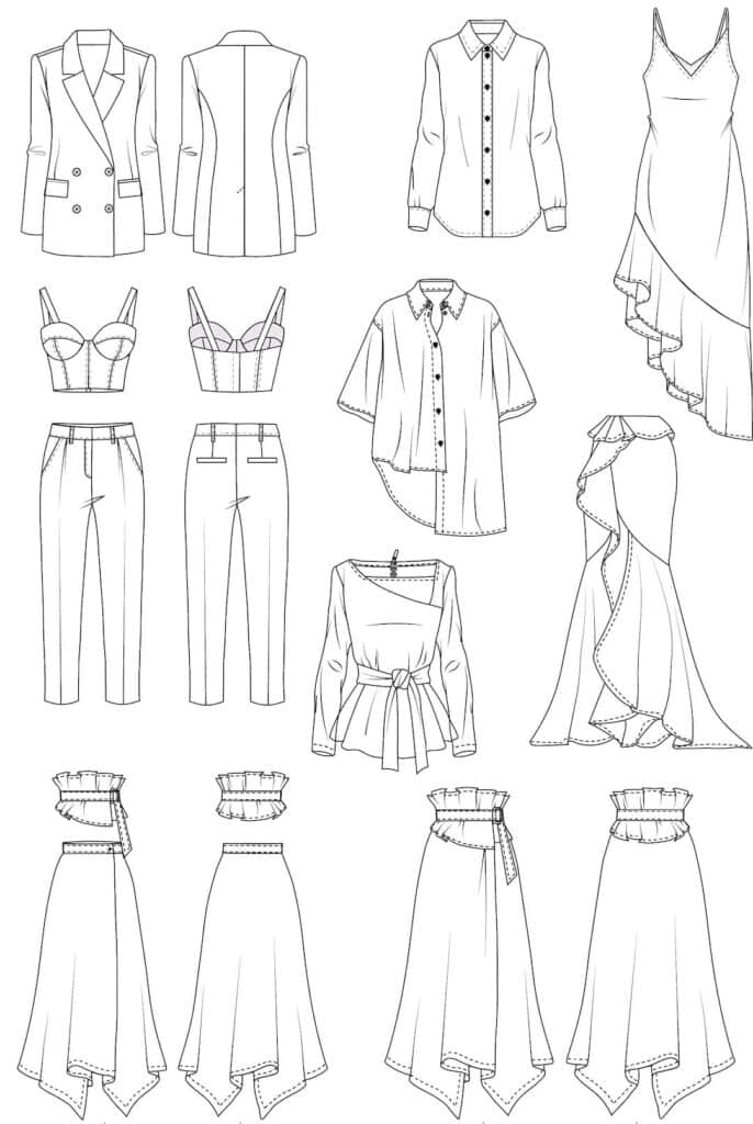
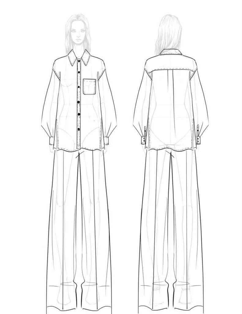
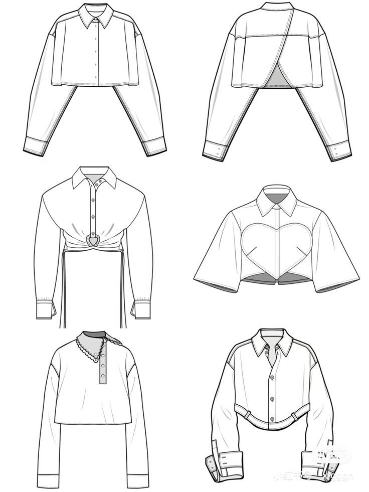
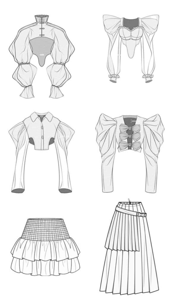
Fashion technical drawing creates flat sketches and construction details for garment production. You develop technical flats, spec sheets, and pattern layouts that guide manufacturing processes.
Technical flats show garments without stylistic interpretation. These drawings display proportional accuracy, construction lines, and design details from front and back views.
Spec sheets document measurements and construction requirements. You include grade rules, seam allowances, and construction methods for pattern makers and sewers.
Pattern layouts optimize fabric usage and cutting efficiency. These drawings show pattern piece placement, grain lines, and notch locations for accurate assembly.
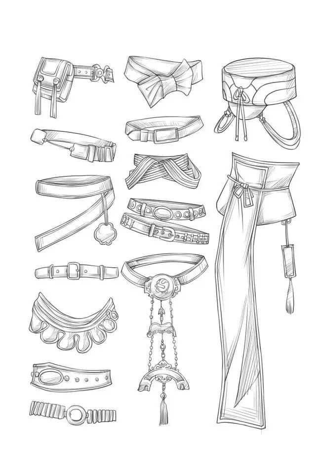
Construction details illustrate complex design elements. You draw enlarged views of pockets, closures, and decorative elements with specific assembly instructions.
Fit specifications ensure consistent sizing across production runs. You document key measurement points and fitting standards that manufacturers follow during garment construction.
Communicating Design Intent and Collaboration
Technical drawings serve as the primary communication tool between designers, manufacturers, and suppliers. Clear documentation of specifications and collaborative review processes ensure your design vision translates accurately into the final product.
Conveying Technical Product Specification
Your technical drawings must communicate every critical detail through precise visual language. Accurate dimensions and consistent line weights form the foundation of clear technical communication.
Use standardized symbols and notation systems that manufacturers recognize immediately. Include material specifications, surface finishes, and tolerance requirements directly on your drawings.
Create detailed section views to show internal components and assembly relationships. Cross-reference related drawings using clear numbering systems and revision tracking.
Essential specification elements include:
- Dimensional accuracy with proper tolerancing
- Material callouts and grades
- Surface finish requirements
- Assembly instructions and sequences
Layer your information logically from general assembly views to specific detail drawings. This hierarchy helps manufacturers understand both the overall concept and individual component requirements.
Include notes for critical processes or special handling requirements. Your drawings should answer questions before they arise during manufacturing.
Collaborating with Manufacturers and Suppliers
Establish clear communication channels with your manufacturing partners from the project start. Share preliminary drawings early to identify potential production challenges and cost-saving opportunities.
Use feedback loops to refine your designs iteratively. Manufacturers often suggest improvements based on their production capabilities and material expertise.
Create drawing review schedules that align with production timelines. Regular check-ins prevent costly changes during later manufacturing stages.
Document all design changes and communicate updates immediately to all stakeholders. Use revision clouds and detailed change logs to highlight modifications.
Effective collaboration practices:
- Schedule regular design reviews
- Maintain version control systems
- Document decision rationales
- Share manufacturing constraints early
Encourage manufacturers to mark up drawings with questions or suggestions. Their practical experience often reveals design optimization opportunities you might miss.
Reviewing and Revising Drawings
Implement systematic review processes before releasing drawings for production. Check dimensional consistency, material specifications, and manufacturing feasibility.
Use standardized checklists to ensure completeness across all drawing elements. Review tolerances against manufacturing capabilities and functional requirements.
Create revision tracking systems that clearly identify changes between drawing versions. Consistent revision practices prevent confusion during manufacturing.
Conduct cross-functional reviews with engineering, manufacturing, and quality teams. Each perspective catches different types of errors or improvement opportunities.
Review checklist items:
- Dimensional accuracy and tolerance stack-ups
- Material specifications and availability
- Manufacturing process compatibility
- Assembly sequence verification
Archive superseded drawing versions while maintaining access for reference. Clear version control prevents accidental use of outdated specifications.
Schedule final reviews after incorporating all feedback before authorizing production release.
- 1.5Kshares
- Facebook0
- Pinterest1.5K
- Twitter0
- Reddit0

